Writing on Transparent Substrates
One of the Vistec's major weaknesses is its problems with writing on transparent substrates, such as fused silica. The reason for the problem is the system's focusing mechanism-- it uses a laser bounced off the sample surface to measure the relative sample height, which it then uses to calculate the beam focus settings via a look-up table. The laser is a standard 633nm HeNe? laser, so anything not reflective at that wavelength is going to give the height meter either no reading or (worse) a random reading from internal and back-side reflections.
Luckily there are workarounds, both in the system software and via processing tricks.
Method 1: Ignore the problem (noheight)
 If feature size isn't critical, the simplest way to deal with the transparent-substrate problem might be to just turn off the laser feedback and let the system "run blind." The system won't be able to focus in real time so your spot may be up to a factor of two larger than it should be in some places, but if you're making features that are hundreds of pixels wide you can probably live with that.
If you're planning to do this there are a few failsafes that need to be disabled on the system; otherwise your write job will crash when it can't get a reading off the height meter.
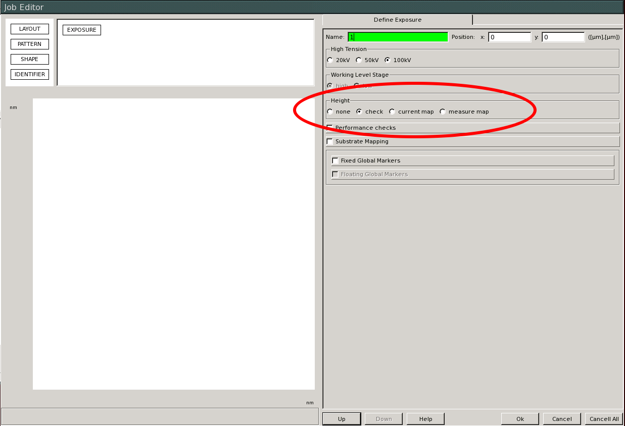
The first thing you need to do is disable the nine-point height check at the beginning of your job. This is done in the Exposure object of CJOB; find the "Height" box and change the option from "check" to "none." If you forget to do this you'll get a bunch of asterisks (or weird readings like -150um) in the height map, usually followed by a job crash.
The next thing you need to do is turn off real-time height checking; otherwise spurious reflections could send the system way out of focus. This is done by enabling blind-write mode with the command
If feature size isn't critical, the simplest way to deal with the transparent-substrate problem might be to just turn off the laser feedback and let the system "run blind." The system won't be able to focus in real time so your spot may be up to a factor of two larger than it should be in some places, but if you're making features that are hundreds of pixels wide you can probably live with that.
If you're planning to do this there are a few failsafes that need to be disabled on the system; otherwise your write job will crash when it can't get a reading off the height meter.
The first thing you need to do is disable the nine-point height check at the beginning of your job. This is done in the Exposure object of CJOB; find the "Height" box and change the option from "check" to "none." If you forget to do this you'll get a bunch of asterisks (or weird readings like -150um) in the height map, usually followed by a job crash.
The next thing you need to do is turn off real-time height checking; otherwise spurious reflections could send the system way out of focus. This is done by enabling blind-write mode with the command noheight on. The script will disable real-time height checking and prompt you for a fixed height to use for focusing instead. If you're using the 4" wafer holder, you can safely put in zero here. If you're using the piece part holder, things are a little trickier since the height can be arbitrarily set by the leveling screws. The laser mounted on the alignment microscope is exactly the same as the one on the system height meter, so it isn't going to give you reliable height readings (usually it reads back-side reflections). The easiest way to get a good height estimate is to mount a piece of reflective material on the stage next to your sample and measure that (you can also level the stage this way). Once you have a number for the absolute height, write it down and enter it when the noheight script prompts for it.
For best results with this method, make sure your sample is 1) as level as possible over the area you're writing in the alignment microscope, and 2) the absolute height in the alignment scope is as close to zero as you can get it (if you can't zero it, just enter the absolute height as the focus height when prompted). Again, the best way to verify both leveling and the absolute height is with a piece of reflective substrate mounted as close to your sample as you can get it.
Method 2: Single-point height measurement (blindjob)
A slightly more accurate way to write without height-meter feedback is to use a reflective region of your substrate to get a single height measurement, then using that as the fixed height during the write. Obviously for this to work you'll need a reflective region on the substrate, ideally at least 5x5mm so the laser dot can reflect cleanly. Large alignment marks, contact pads, or similar features usually work well for this.
As in method 1, you'll need to set the Height option to None in Cjob or this won't work.
Use the alignment microscope to locate the reflective region you'll be using on your sample and record the coordinates (relative to the Faraday cup, as you would with alignment marks). Once your sample is loaded in the system, drive to the reflective area with a relative move and measure the height with the command pg get height /measure. Ideally you'll get a number between +50 and -50 um; if not, use the SEM to make sure you're centered over the reflective area correctly. Write down the absolute coordinates of the reflective feature for later.
Execute your job using the blindjob command instead of job. The Blindjob script will prompt you for the (absolute) coordinates of the reflective area, which you wrote down earlier, so put them in when it asks. It then drives to the reflective area, takes a single height measurement, and uses that as the height during the write. You don't need to do anything after the write, as the script automatically resets the system state when the job finishes.
Again, for best results you'll want to get the sample as level as possible in the alignment microscope here. The best (or least bad) way to level a transparent sample is to mount a piece of reflective material on the stage, as close to your sample as you can get it, and use the reflective piece for leveling. Absolute height isn't critical, since the height will be measured before the write.
Method 3: Add a reflective layer
The best, most accurate way to deal with the transparent-substrate problem is to make your substrate less transparent. The easiest way to do this is to deposit some metal on top of your resist layer, then remove it before development. For most metals, 30-40 nm of thickness is enough to get an optically reflective film. Metal can be deposited via sputtering or thermal evaporation; avoid e-beam evaporation, as the x-rays produced will expose your resist.
If you're using PMMA resist, the easiest metal to use is gold. Use the AJA-2 sputtering system to put down 30-40nm (please don't use the SEM sputterer for this, you'll wear out the target!), then remove it after exposure with ~1 min of immersion gold etch (KI solution,etch rate ~3nm/sec). See the section in the charging guide for details on using gold films; the process is identical except for the metal thickness and gold etch time.
You can also use ESpacer , although since the polymer is an acid it isn't compatible with chemically-amplified resists such as NEB31. See the section on charge suppression for ESpacer processing tips; the only thing different in this case will be the thickness of the metal film.