EBPG Standard Operating Procedure
General Notes
- This document is intended as a refresher for people who have already had full training on the system, NOT as a substitute for training! Contact Kevin Roberts if you need system training (rober074@umn.edu)
- When handling sample holders, please take extra care not to drop them or touch/damage the reference plate assembly where the Faraday cup is located. Damage to the holders is expensive and time-consuming to fix
- The sample holders are very precisely-machined pieces of equipment. If you’re having trouble fitting one into the cassette, jig, or alignment microscope, you’re probably doing it wrong. Double-check that everything is lined up and fitting together correctly, NEVER try to force a holder into anything!
- When specific areas of a holder are referred to in this guide (e.g. “the upper-left corner of the holder”), the assumption is always that the “claw” on the holder that the load arm attaches to is facing you, the user.
- When the guide refers to linux shell (terminal) commands, it uses the standard format of
command <param> [param], where <param> is a non-optional parameter and [param] is an optional parameter. Don't include the brackets when typing the actual commands.
Loading the Sample Holders
Load your sample onto the holder. The exact method varies by holder:
Loading the Mask Plate Holder
- If there is a mask currently in the plastic jig, remove it (see Unloading the Sample Holders section)
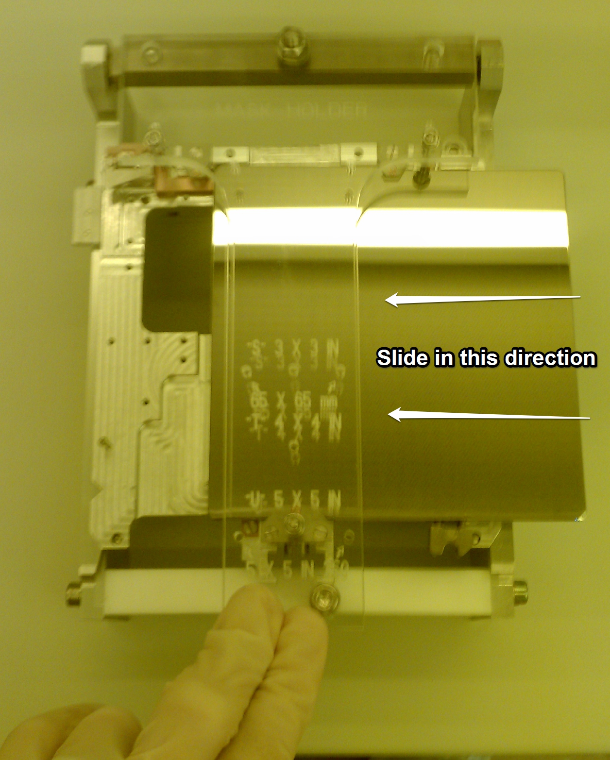
- Slide the holder all the way into the plastic jig assembly with the load-arm “claw” facing you
- Bring the swivel arm on the jig forward and gently use it to press the three copper spring-clips on the holder down.
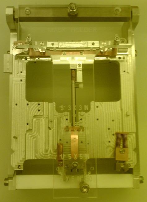
- With the clips still pressed down, slide the mask into the holder from the right, making sure it is flush against the back of the holder and making contact with the stop pin on the left.
- Release the spring clips
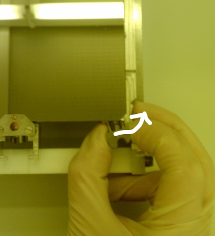
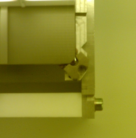
- Engage the spring-lock mechanism on the lower-right of the holder by pulling it out approximately 1”, swiveling it 45°, and releasing the spring so it clamps the corner of the mask plate
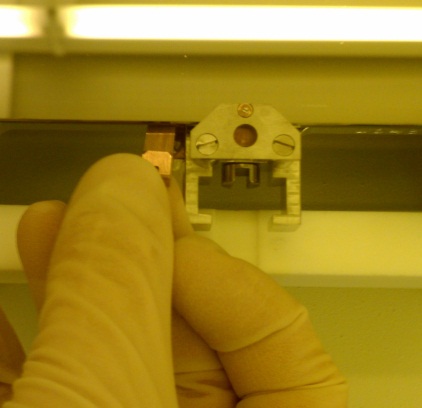
- Attach the copper grounding clip to the mask just to the left of the loader claw, making sure it is contacting the copper clip below the mask on the holder. Attaching the clip can take some practice; if you're having problems, ask for help.
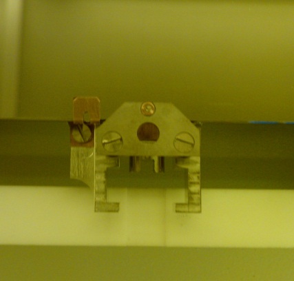
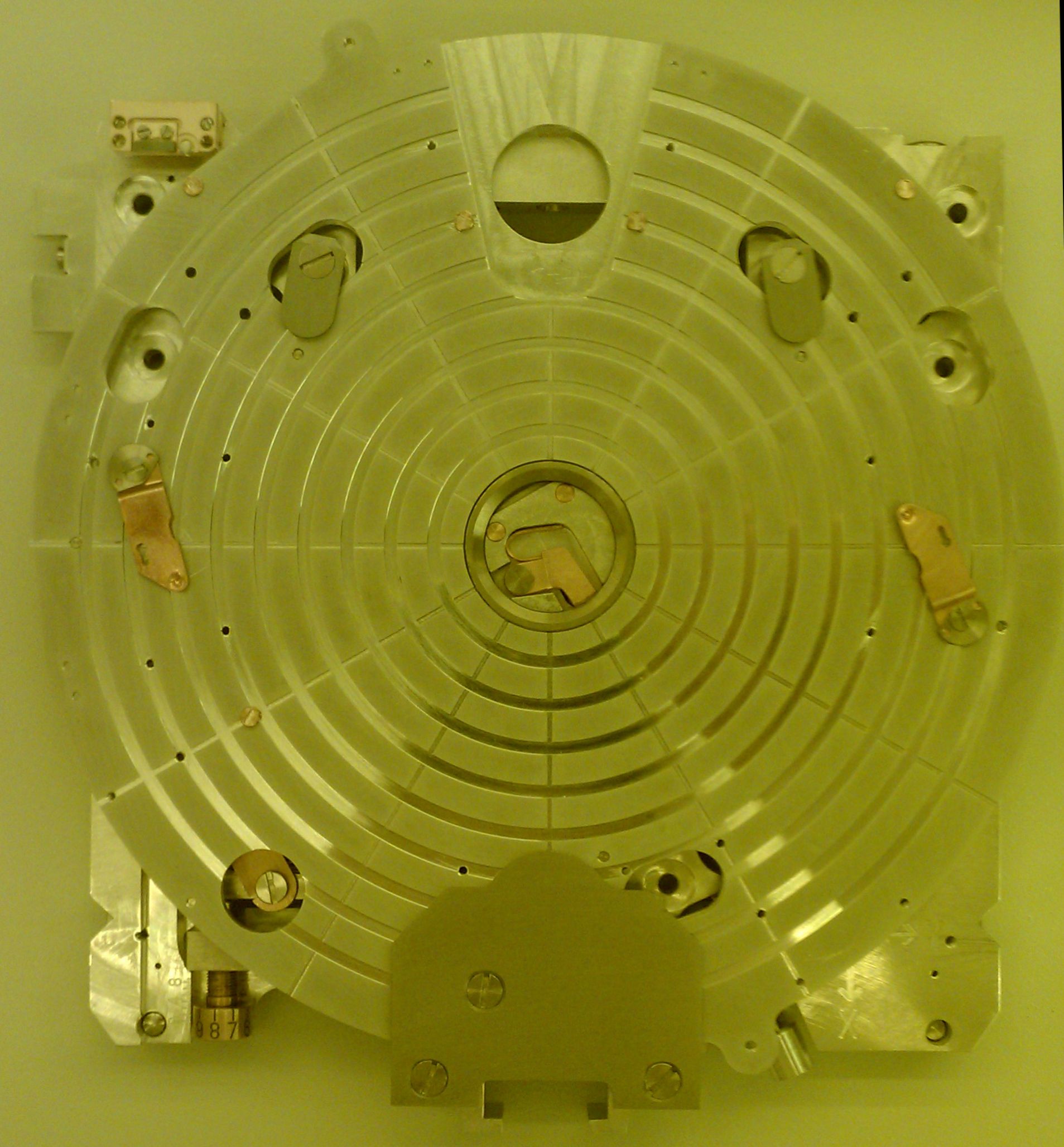
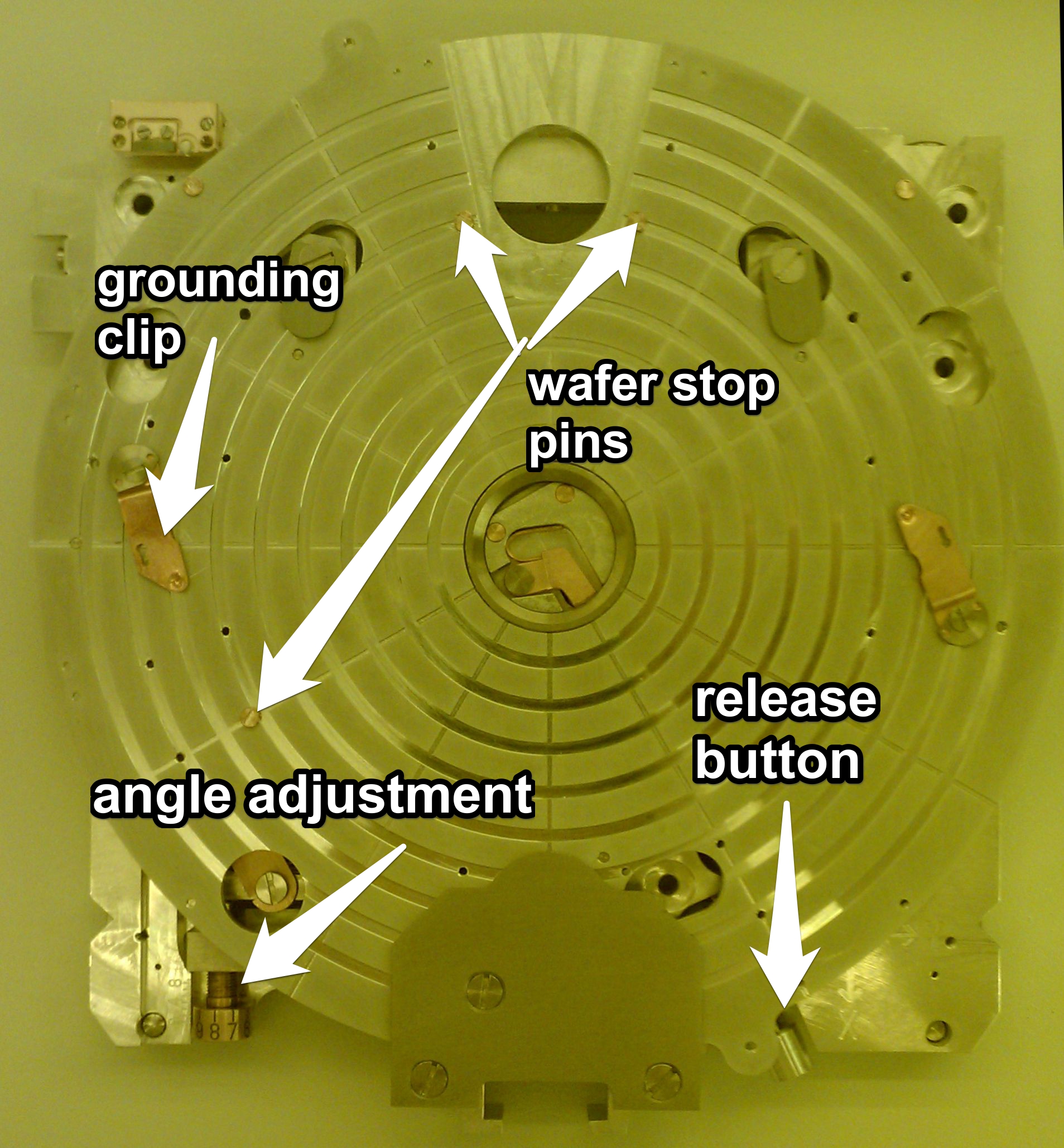
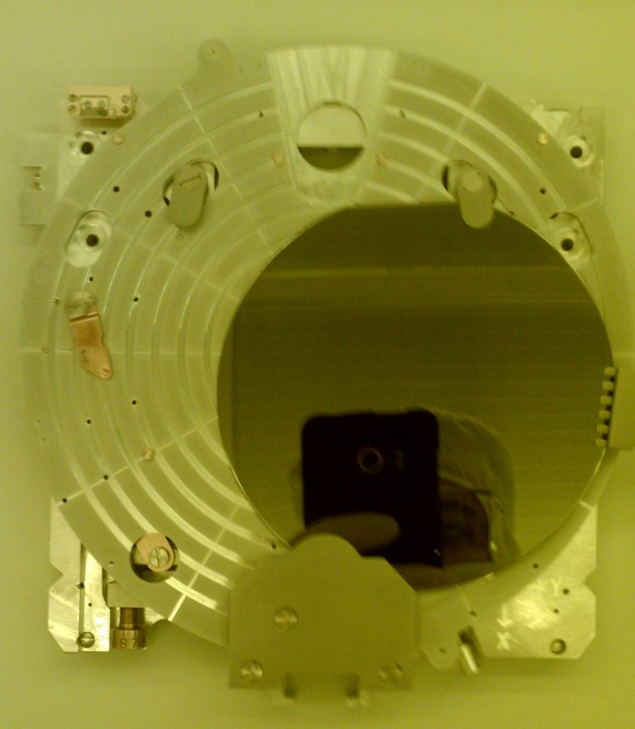
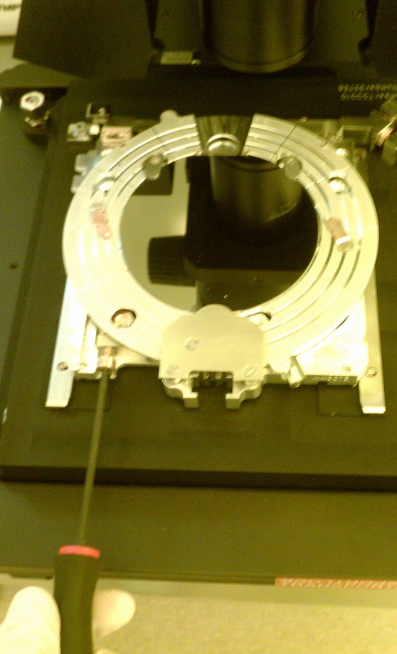
Loading the 4" Wafer Holder
- If there is a wafer on the holder, remove it (see Unloading the Sample Holders section)
- Firmly push the stage down with both hands until you hear a click sound
- With the loader claw facing you, slide your wafer in from the right, over the copper clips and under the metal stops in the holder tray. Make sure the wafer flat is flush against the two parallel stop pins and the edge of the wafer is also contacting the third pin on the stage.
- Using the special tool (or tweezers if the tool is missing), lift the copper clips and swivel them so they’re pressing down on the wafer. Hook the tool through the keyholes in the clips to move them; try to avoid bending the clips excessively here
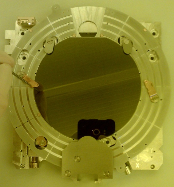
- With the clips holding the sample in place, press the metal button to the lower-right of the stage to release the stage lock and clamp the wafer against the top-reference stops.
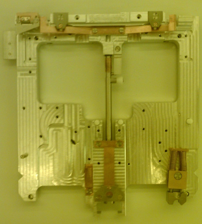
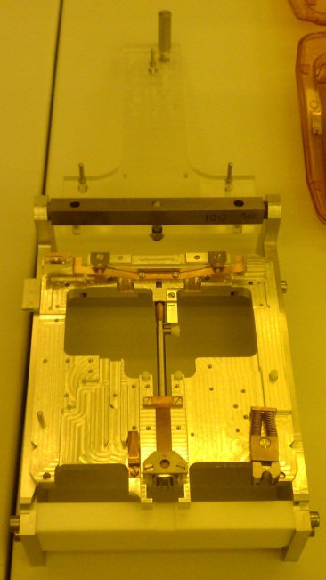
Loading the Piece Part Holder
- Remove any samples currently on the stage you wish to use (see Unloading the Sample Holders section)
- Make sure the back of your sample is clean and free of any tape, resist, or other material that could keep it from sitting flat against the stage
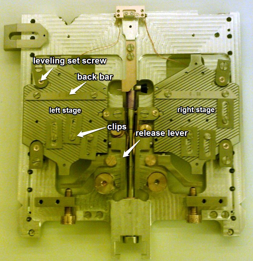
- Note that the left stage is specifically leveled for standard Si wafers that were purchased in the NFC. If you have a non-standard wafer (SOI, GaAs?, thin Si, etc), or your wafer originated somewhere besides the NFC, use the right-hand stage
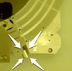
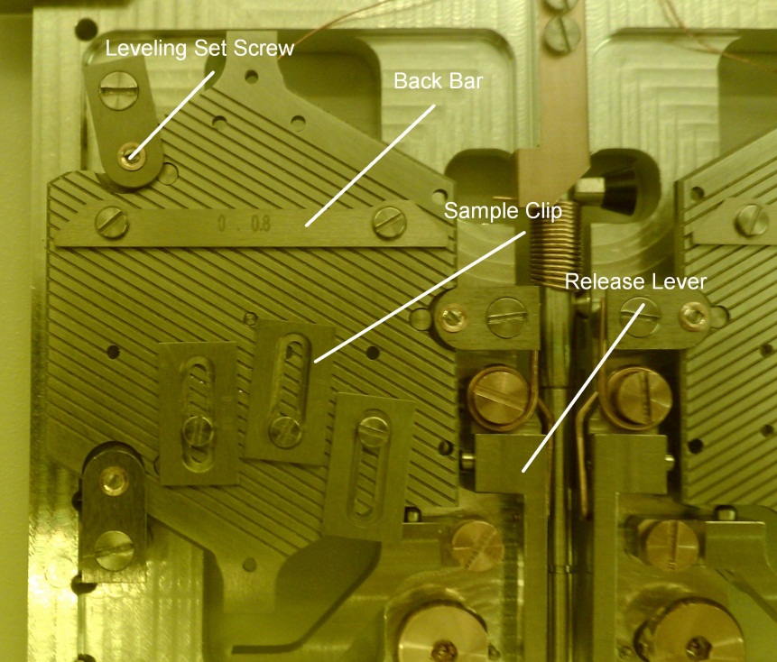
- Using a small screwdriver, loosen the clips on the applicable stage and slide your sample in, making sure it firmly contacts the long bar attached to the stage
- Moving the clips around is fine if necessary; there are several tapped holes on each stage where the clips can be screwed in
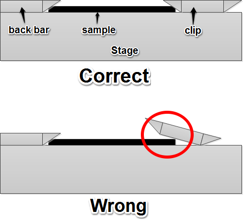
- Move the clips so that they hold the sample between the clip and the back bar and tighten them down. Note that the edges of both the clips and bar are beveled inward, so the clip does NOT have to be on top of the sample to hold it in place (doing this will damage the clip). Just push the clip forward until it is firmly flush with the sample and that should provide enough force to hold it.
- Tighten the screws on any clips not being used to hold the sample
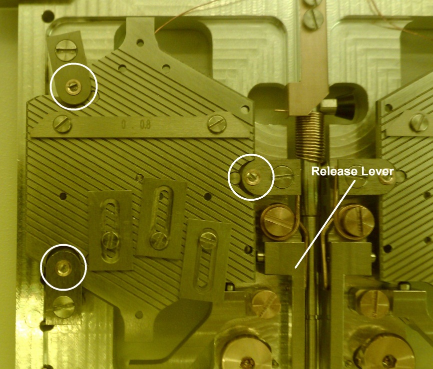
- Press the release lever to the right of the wafer several times to make sure the stage is pressed against its leveling set screws.
- Level the sample (see section on leveling for details)
Write Preparation
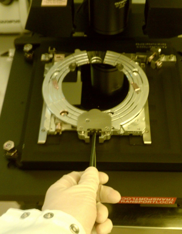
- Load your holder and sample into the alignment microscope by sliding it into the microscope tray, load-arm claw facing you.
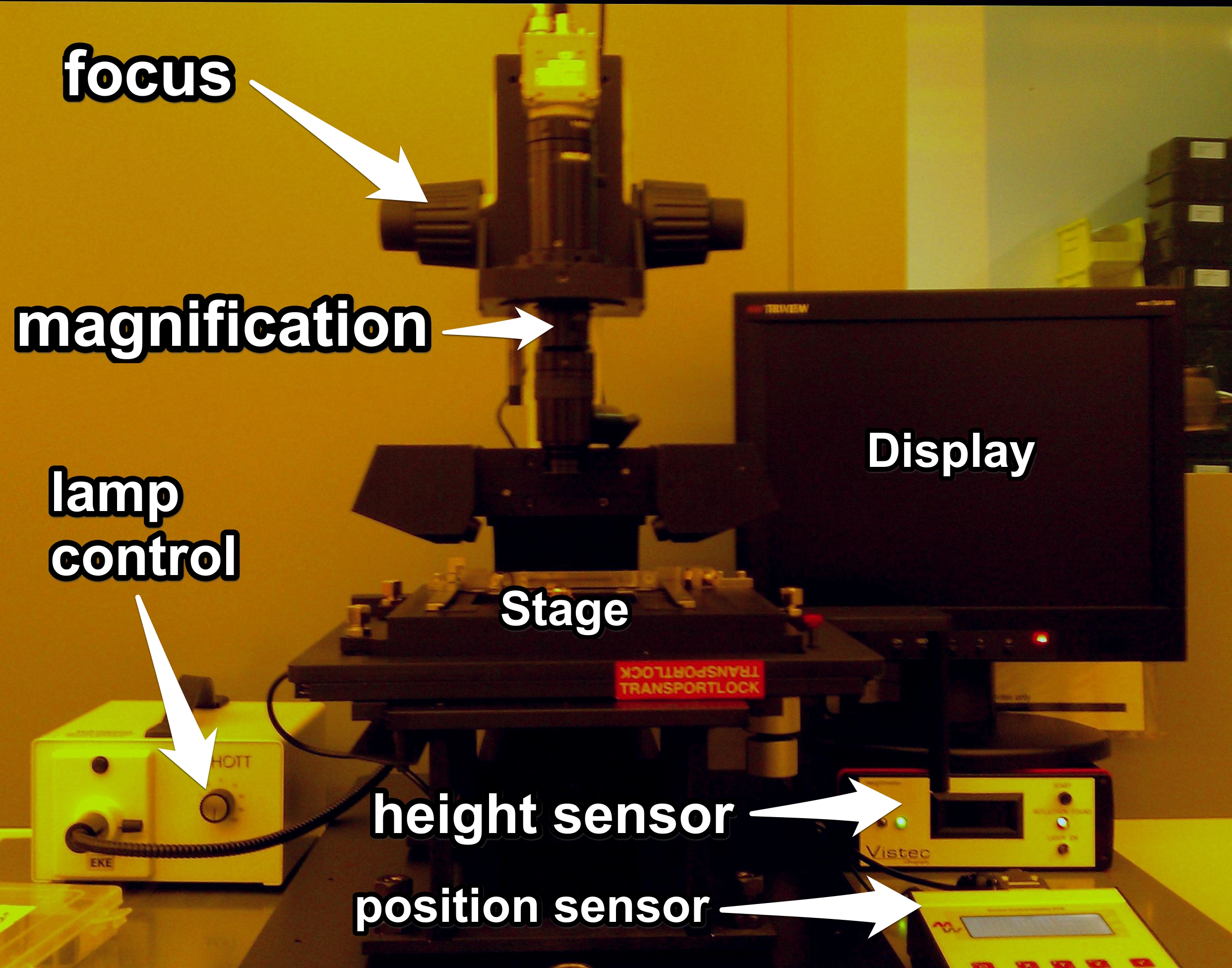
- Turn on the monitor, height meter, and lamp. Turn up the lamp power until you see an image on the monitor.
- Clamp the holder into the tray by giving the large screw in the center of the load-arm claw a quarter-turn clockwise (until you feel a “click”) with the butt end of a pair of tweezers. Do not over-torque this screw, as the clamping assembly is easily damaged.
Stage Leveling (piece part holder only)
If you are using the piece part holder, you will need to manually level your sample so the beam stays in focus during your write.
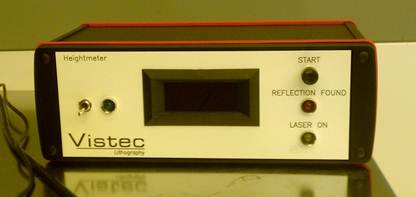
- Turn on the laser height sensor display to the right of the microscope using the toggle switch to the left of the LCD display. Press the start button to the right if no number is displayed (if the display goes out during the leveling process, just press the button again)
- Move the height meter probe (red laser dot) to approximately the center of your sample
- Verify that the height displayed on the height-meter display is between -50 and +50 μm. If it is not, and particularly if the height is completely out of range (-1 or +1 displayed for too low or too high, respectively), do the following:
- Press the stage down firmly and bring it back up with the release lever several times. Sometimes the stage isn’t fully flush with the height set screws.
- If releasing the stage doesn’t fix the problem, give each height set screw (the very small screws at the edges of the three metal clamps above the stage) ˝ to ľ of a turn clockwise (if the height is too high) or counterclockwise (if the height is too low). Press the release lever several times and re-measure. Keep adjusting all three screws simultaneously until the absolute height is well within the -50 to +50 μm range.
- With the absolute height approximately correct, it’s time to level the stage. Zero the position-measurement display (the LCD display to the right of the microscope) by pressing the X and Y buttons.
- For the stage to be level to within the EBPG’s focus-compensation tolerance, there must be less than 1 μm of height change for 1 mm of translation in both the X and Y directions. To measure this, note the value on the height meter, move in either X or Y 1 mm using the position readout, and note the new height-meter value.
- Note that the stage needs to be leveled in both X and Y. It’s generally easiest to pick an axis, get it level along that axis, and then work on the other one. You may need to iterate between the two a few times.
- To change the tilt of the stage, adjust the three set screws in the metal clamps. If one side of the stage is too HIGH, turn the set screw CLOCKWISE to lower it. If it is too LOW, the set screw should be turned COUNTERCLOCKWISE to raise it.
- When adjusting the X axis, try to adjust the top-left and bottom-left screws concurrently (e.g. turn one a quarter-turn clockwise and the other a quarter-turn counterclockwise) to minimize disruption of the Y-axis leveling
- Similarly, when adjusting the Y-axis, use only the right-hand screw to avoid changing the X-axis leveling
- The set screws give approximately 200 μm of vertical translation per full turn, so adjusting in small steps (1/4 to 1/8 of a turn at a time) is recommended.
- After each set screw adjustment, pull the release lever a few times to make sure the stage is flush with the new set screw positions before measuring
- Leveling the stage is an iterative process; be prepared to measure, make a change, measure again, make another change, etc. It can be frustrating and is as much a matter of practice as anything else.
- If your height numbers make absolutely no sense, it’s possible that you have your sample clamped in too tightly and its surface is bowed slightly, there are particles under the mounted sample, or the clips aren't centered correctly. Try re-mounting your sample and see if things get better.
- If you are using an authorized sample in the left (NFC Si only) stage, you should only need to do minimal leveling. If the numbers are way off and pressing the release lever does not fix it, verify that your sample is clamped in properly.
Rotational Adjustment (aligned writes only)
If you are doing an aligned write on either the piece-part or 4” wafer holders, you will need to rotationally align your sample to within 0.2° of horizontal by doing the following:
- The easiest way to do this is to find two parallel alignment marks spaced over 1 mm apart. To be within 0.2°, moving between marks spaced 1 mm apart in one axis should give you a position variation of less than 3.5 μm in the other axis. Use the 3mm Allen screwdriver near the microscope and the brass rotation-control screw in front of each stage to adjust the stage angle until this is true.
Write Location
Finally, you will need to locate the area on your sample you want to write on.
- Find the Faraday cup on the reference plate. To the naked eye, it looks like a small metal disc ~1 mm in diameter. In the microscope, a small hole will be visible in the center of the disc. Find the Faraday cup, center it on the screen, and zero the position readout in both the X and Y axes (press the X and Y buttons)
- Move from the Faraday cup to your write area
- For non-aligned writes, this is the position where the CENTER of your write job should be placed
- For aligned writes, this is the three (or four) positions where your three (or four) global alignment marks are in the approximate center of the monitor.
- It may be difficult to find your alignment marks at the current magnification. If this is the case, rotate the magnification control on the microscope barrel and refocus as necessary. Try to use the same magnification when locating both the Faraday cup and your marks.
- Jot down your center position (non-aligned writes) or mark positions (aligned writes) from the position meter. Now you can find these positions in the system by moving to the Faraday cup and then doing a relative move to the coordinates you just recorded.
- Release the holder from the microscope by turning the lock screw counterclockwise Ľ of a turn and sliding it out.
- Make sure the microscope light, monitor, and height meter are turned off.
System Loading
- Activate the system with Badger. This will turn on the monitors.
- The only two windows that should be open on the desktop are CSYS (the vacuum system schematic) and CSEM (the SEM/beam tracking software). If anything else is open, close it (especially terminal windows)
- If CSYS/CSEM aren’t open, use the desktop icons to start them up.
- Check CSYS to make sure there isn’t a holder in the chamber. If there is, unload it to an empty cassette position using the
subu command
- Vent the airlock using the set lock vent button in CSYS. The airlock should come to atmosphere in approximately two minutes.
- If you have to load your sample onto a holder, level it, or do anything that will take more than a few minutes, it’s a good idea to pump the loadlock down while you work. Leaving the lock vented for more than a few minutes will drastically increase pumpdown time and is bad for the turbopump.
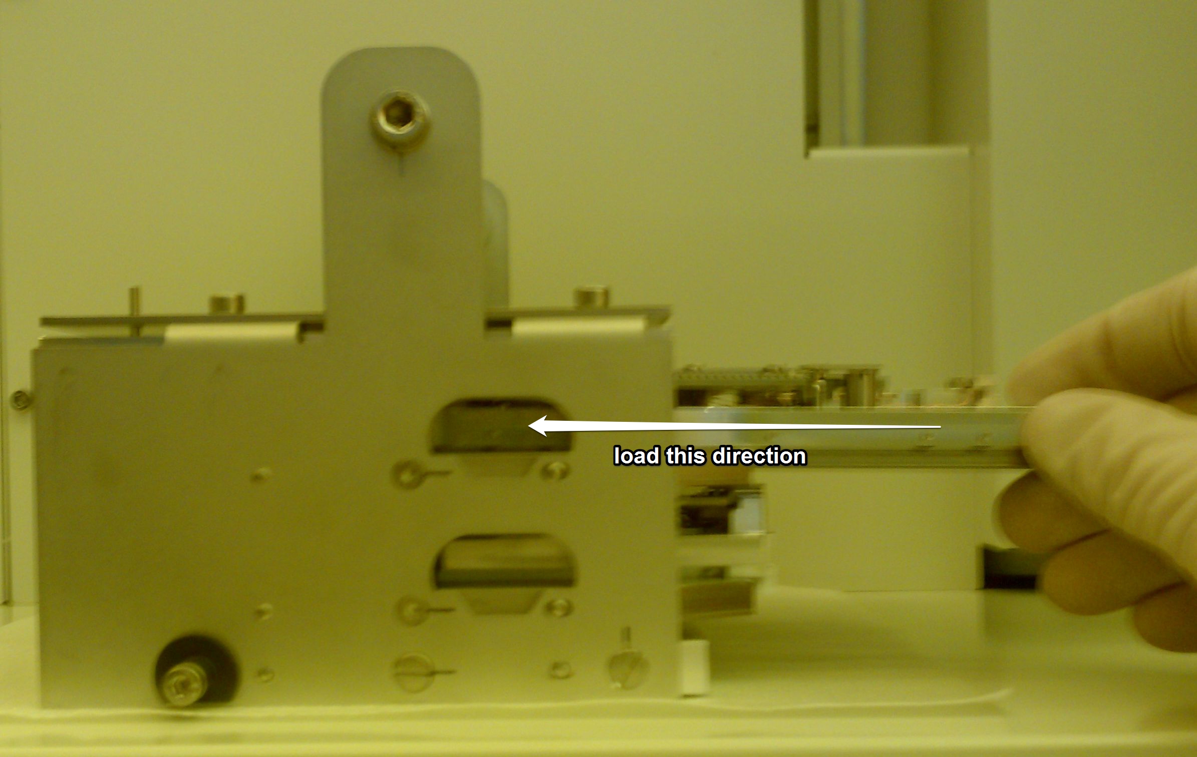
- Open the airlock and remove the holder cassette. Carefully load the holder with your sample mounted on it into the cassette by sliding it in from the right until it clicks into place. Make sure the holder is seated on the rails in the cassette correctly; it should slide in with almost no force.
- For detailed instructions on loading your sample onto the appropriate holder, see the Loading the Sample Holders section.
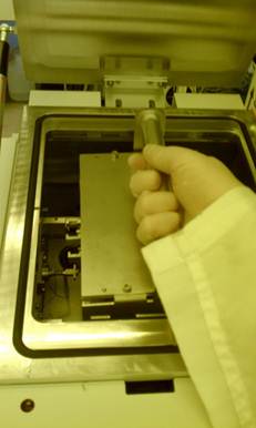
- Replace the cassette in the airlock, making sure to press it down until it clicks into place (the click will come from the side nearest to you).
- Close the airlock lid and pump it down using the set lock vacuum button in CSYS. The airlock will begin pumping down, and should reach its crossover pressure of 5 × 10⁻⁵ torr in approximately five minutes under normal circumstances.
- Open a terminal window using the icon on the desktop and switch to your environment using the
ce <username> command, where username is the username is the one you were assigned on the CAD computer. You should do this each time you open a terminal window, as it tells the system where to look for your job, pattern, log, and other files.
- Load your sample holder into the system using the
subl <position> command (that’s a lowercase “L”, not a “1”), where position is the cassette position your holder is loaded into (1 for top, 2 for bottom).
- Use the
pg select holder [HID] command to tell the system which holder is loaded. If you know the HID number of the holder you can specify it in the command line. If not, leave it blank and a list of available holder types will pop up, with the holder ID numbers on the left. Type the number that corresponds to your holder at the prompt.
- Move to the holder’s reference mark and locate it by using the
pg move mark (shortcut is mvm) command with no additional arguments. This will verify that 1) the correct holder is selected, 2) the holder reference plate containing its reference marks and the Faraday cup is not damaged, and 3) the beam and detectors are working correctly.
- If the system fails to find a mark it will return an error; this almost always means the wrong holder is selected. If you are absolutely certain the selected holder is the correct one, remove the holder, vent the system, and inspect the reference plate for damage
- A successful mark location will return the terminal window to a prompt with no output.
- Move to the Faraday cup and measure the current by using the
pg measure current (shortcut is mea_c) command. Again, this verifies that 1) the Faraday cup is undamaged and 2) the column is functioning correctly. If everything goes right, the last beam current used on the system should be displayed.
- If a beam current of zero is read, verify that the beam source is energized by using the
pg get filcur command. You should read a filament current of ~2.35 A. If it’s zero, the gun is off and will need to be restarted.
- The current you measure here is just the last current used by the last user of the system; its actual value doesn’t matter. All you want to verify is that there are no errors when you try to measure and that the current isn’t zero.
NOTE: If you’re comfortable with it, advanced users can bypass steps 9-12. Use the command load <position> [HID] to automate all four commands. Note that an error in any of the commands will stop the entire sequence. If everything executes correctly, the stage will be positioned at the Faraday cup, ready for a relative move to your center/alignment marks.
Non-Aligned Writing
NOTE: This section assumes that you have already used CJOB to generate a .job file. Consult the CJOB Quickstart or the CJob manual for instructions on how to do this.
- If the stage is not already there, move it to the Faraday cup by using the
pg measure current (or mea_c) command
- Use the vector between the Faraday cup and your write site that you recorded earlier on the alignment microscope to move the stage to the area you wish to write on using the command
pg move position X,Y –-rel (shortcut: mvrl X,Y), where X,Y is your coordinate pair
- Note that the default units on the EBPG are microns, but the units on the microscope position reader are millimeters. You can override the default units by specifying millimeters in the command, e.g.
pg move position 38mm,-10mm --rel
- The column is now situated above the center of your write area. It shouldn’t be necessary, but you can inspect the area visually using CSEM by clicking the sem on button.
- If you decide to inspect the sample, ALWAYS switch to a low beam current (<1 nA) first to avoid exposing your resist! Use the command
pg archive restore beam mybeam (shortcut: beamload mybeam) to load a beam (where mybeam is the name of a beam profile, e.g. 1na_300um), and the beamlist command to get a list of available beam profile names.
- If you haven’t already, use the
ce <username> command to change into your environment in the terminal
- Switch into your jobs directory (
cd jobs) and execute your job using the command job myjob.job <holder ID> <cassette position> X,Y
- Use the
ls command to see the list of files in the jobs directory if you can’t remember the filename
- Do not try to run .cjob files this way, those are data files that can only be read by CJOB. Job files that can be executed by the system have the extension .job
- Holder ID is the ID of the holder you’re using (you also used it with the
pg select holder command earlier). If you can’t remember it, the holders command will bring up a list of the holders and their IDs.
- Cassette position is the cassette slot the holder you want to write on is located in. Since you should always have manually loaded your sample onto the stage and done the checks mentioned earlier prior to writing, the value you enter here should always be 0, which corresponds to “currently on the stage.”
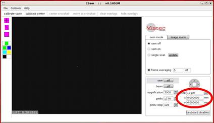
- The units of X and Y are microns, and unlike the units in almost every other pg command cannot be changed. Moreover, the coordinates used for X and Y are absolute stage coordinates unless specified otherwise.
Luckily, you can use CSEM to read the absolute position of the stage (which should be located where you want to write) in the lower-right corner of the window at any time. These units are in millimeters too, but can be easily converted to microns by throwing out the decimal point.
- By default the center position is in absolute coordinates, although you can specify it with respect to the Faraday cup by using the
–f switch after the job file name in the command line if you like (e.g. job myjob.job –f <holder ID> <cassette position> X,Y
- If X and Y are not specified, the system uses the defined center of the specified holder as the center of the write. Depending on what you’re trying to do, this may or may not be perfectly fine.
- Executing jobs can be greatly simplified using the
writejob shortcut, which eliminates a lot of the junk in the job command line. See the section on useful shortcuts for details on using it.
- Lots of text will begin scrolling down the window as the system performs a series of calibrations and then writes your pattern. You don’t have to worry about reading any of this (it’s being stored in a file in your
logs directory) but it’s always a good idea to sit and watch it until the system starts actually writing (you’ll be able to watch the beam trace your patterns in CSEM when this happens). See the Troubleshooting section for a list of errors that can stop the write at this point and how to work around them.
- You can monitor the job’s progress graphically with CPRO. Run it from the desktop icon or by typing
cpro
- When your write is finished, unload the holder to the load lock with the
subu command
Aligned Writing
- Move to the Faraday cup using the
pg measure current (or mea_c) command
- Verify that the system can find each of your global alignment marks and confirm their location by using the following process for each mark:
Drive to the Faraday cup with the mea_c command, then drive along the vector to the mark you measured in the alignment microscope with the command mvrl X,Y, where X,Y is your vector (default units are microns). Turn on SEM mode in CSEM; you should be in the vicinity of your mark, although since the alignment microscope isn’t very accurate you may need to zoom out to 200X to find it. Double-click your mark in the SEM view window to center it, then have the system try to locate it with the findmark <markname> command, where <markname> is the name of your mark definition.
- The full list of alignment mark definitions can be viewed using the command
marklist. Make sure you have the system looking for the correct mark type!
- If the system can’t find a mark and returns an error, verify that the marktype is correct, you didn’t mistype the coordinates, and that you have the mark visually centered in the CSEM window. If all of these things are good, see the troubleshooting section on alignment mark location failure.
- Remember to return to the Faraday cup with
mea_c between trying to find each mark, since your mark coordinates are all relative to that position.
- Write down the absolute coordinates of each mark for later after the system successfully finds it
- To execute your write, use the command
job myjob.job <holder ID> <cassette position> x1,y1 x2,y2 x3,y3 x4,y4 . Everything about this command is identical to the one detailed in the non-aligned write procedure except the coordinates.
- The
xn,yn coordinate pairs in the job command line define the position of the global (exposure-object-level in CJOB) alignment marks. There needs to be at least three of these for an aligned write, and an optional fourth can be used for keystone correction if desired (usually unnecessary)
- The easiest thing to get wrong here is the order of the marks. In CJOB, the global alignment mark coordinates are defined in boxes that go from left to right in the window. The mark positions in the command line have to follow the same order or the system will fail to find them and error out. If the job crashes immediately after finding the marks check the order of the marks in CJOB and make sure you’re specifying them correctly
- All coordinates here are in microns and cannot be changed. By default they are in absolute coordinates, although you can specify them with respect to the Faraday cup by using the
–f switch after the job file name in the command line if you like (e.g. job myjob.job –f <holder ID> <cassette position> x1,y1 x2,y2 x3,y3 x4,y4 ).
- Executing jobs can be greatly simplified using the
writejob shortcut, which eliminates a lot of the junk in the job command line. See the section on useful shortcuts for details on using it.
- Lots of text will begin scrolling down the window as the system performs a series of calibrations and then writes your pattern. You don’t have to worry about reading any of this (it’s being stored in a file in your
logs directory) but it’s always a good idea to sit and watch it until the system starts actually writing (you’ll be able to watch the beam trace your patterns in CSEM when this happens). See the Troubleshooting section for a list of errors that can stop the write at this point and how to work around them.
- You can monitor the job’s progress graphically with CPRO. Run it from the desktop icon or by typing
cpro
- When your write is finished, unload the holder to the load lock (see unloading the holders section)
Unloading the Sample Holders
- Use the command
subu <caspos> to unload the holder to the airlock, where caspos is the cassette position number to unload to (1 is top slot, 2 is bottom slot).
- Vent the airlock using the set lock vent button in CSYS
- When the airlock is fully vented, remove the cassette containing your holder
- Slide your holder out of the cassette by pushing it out from the claw side
- Remove your sample from the holder. Specifics of this vary by holder type.
Unloading the Mask Plate Holder
(Refer to the section on loading this holder for visuals)
- Slide the holder into the plastic loading jig, claw side outward
- Remove the grounding clip from the mask (attached near the claw) and put it somewhere safe
- Disengage the spring clamp on the lower-righthand corner by pulling it out from the mask, swiveling it clockwise 45°, and gently releasing it.
- Swivel the top of the loading jig forward and press it down gently to release the copper spring clips holding the mask up. Gently slide the mask out from the right side of the holder
- Release the jig arm when the mask is out
Unloading the 4" Wafer Holder
(Refer to the section on loading this holder for visuals)
- Push the stage down firmly with both hands until it clicks into place
- Hook the grounding-clip tool into the keyholes on the copper grounding clips and swivel the clips off the wafer. If the tool is missing, tweezers can be used as long as care is taken not to bend the clips.
- Slide the wafer out to the left (claw should be facing you), over the grounding clips and under the metal wafer stops
- Push the button on the lower-right of the holder to release the stage
Unloading the Piece Part Holder
(Refer to the section on loading this holder for visuals)
- Unscrew the clip(s) holding your sample in place and slide them away from your sample
- Remove your sample from the stage with tweezers
- Tighten the screws to hold all the clips in place and press the release lever to release the stage
Leaving the System
- Load the mark plate holder into the bottom cassette slot. Leave the 4" and piece part holders sitting out on clean wipes
- Place the cassette in the load lock, making sure it clicks when pushed down
- Pump the system down using the set lock vacuum button in CSYS
- Make sure the system is set to a low beam current using the command
beamload 1na_300um. High beam currents will increase deposition on the beam blanker and cause problems with the machine over time.
- Close every window except CSEM and CSYS on the computer
- Clean up any mess you’ve made and remove all of your samples from the EBPG area. Anything left behind may get thrown away
- Sign out of Badger to disable the monitors. The airlock should be pumped down, with the cassette and mask holder inside.
NOTE: Advanced users can use the unload <caspos> shortcut, which unloads the holder and sets the beam current to 1 nA in a single command.